Draw Component Diagram Online Free
Create a UML component diagram
Visio Plan 2 Visio Paket ane Microsoft Visio Professional person 2021 Visio Professional 2019 Visio Premium 2010 Visio 2010 Visio Standard 2010 Visio 2007 Lainnya...Kurang
You lot can create a UML component diagram to prove components, ports, interfaces and the relationships between them.
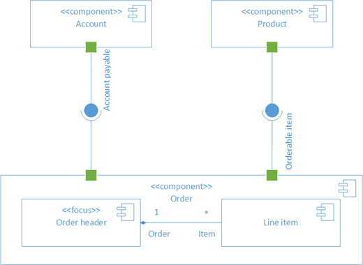
A component in UML represents a modular part of a system. The behavior is defined in terms of required and provided interfaces. A component has an external view with public properties and operations, and information technology has an internal view with private properties and realizing classifiers. The internal view shows how external behavior is realized internally.
First, you lot open the UML Component template and option 1 of the four options. So the UML Component stencil appears, along with shapes that conform to the UML 2.5 standard.
Start a component diagram
-
Start Visio. Or if y'all have a file open up already, click File > New.
-
Go to Categories > Software and Database > UML Component.
-
Select the bare template or ane of the three starter diagrams. When you've picked the template you want, click Create.
-
Y'all should see the Shapes window adjacent to the diagram. If you don't see it, go to View > Task Panes and make sure that Shapes is selected. If you still don't see information technology, click the Expand the Shapes window button
 on the left.
 -
On the View tab, brand certain the cheque box next to Connection Points is selected. This will make connection points appear when you start connecting shapes.
-
At present, elevate shapes you desire to include in your diagram from the Shapes window to the page. To rename text labels, double-click the labels.
Component shapes
When to use
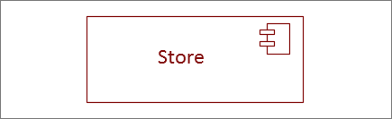
Use component shapes for each functional unit in your organisation or application.
Show or hide stereotype
Right-click the shape to show or hide the stereotype label.

Subsystems
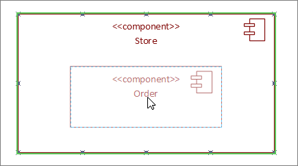
You tin can utilise the component shape as a subsystem shape that contains other components. Simply resize information technology to be larger, and drib other components on height of it. When yous meet the green highlight, let go. From that signal on the larger shape will deed as a container, and the smaller shape will motion with it.
Tip:If a component disappears after dragging information technology on top of another component, then bring it to the front by pressing CTRL+SHIFT+F.
Interface shapes
When to utilise
-
Utilize the Provided Interface shape when you desire to specify the realization of a form/interface.
-
Apply the Required Interface when you desire to specify a dependency on a class/interface.
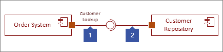
Stride 1
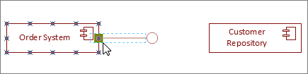
Drag a Provided Interface shape to the folio, and line upwardly the port square with a connectedness point. You know it's connected when y'all see the green highlight around the connection point.
Step 2
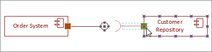
Drag a Required Interface shape to the page, and line up the port foursquare with a connection point as well. You know it's connected when yous run into the green highlight around the connectedness betoken.
Step 3
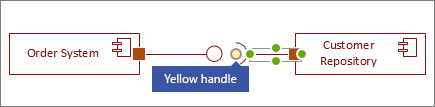
To connect both a Provided and Required interface together, first select the Required Interface shape. Then await for the xanthous handle.
Step 4
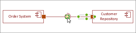
Drag the yellowish handle to connect with the Provided Interface.
Tips for connectors
Straighten connectors
If a connector is taking too many turns, correct-click it, and and so click Straight Connector.
Show multiplicity
If needed, right-click the connector and select Testify Multiplicity. When you're done, iv text boxes announced where you tin add details. If you do not need all the text boxes, delete the ones you lot don't demand.
Change connector blazon
You lot can change a connector type. For instance, you can modify from an Association to a Directed Association. Right-click the connector, and and then click Set up Connector Type.
Make dynamic connections instead of point connections
If you anticipate moving shapes a lot, consider making a dynamic connexion instead of a point connection.
Movement or rotate text on connectors
Nearly likely you'll need to rotate or motility text on your connector lines. Hither's how to do that:
-
Click an empty area of the page to deselect anything that may be selected.
-
On the Home tab, in the Tools group, click the Text Block tool

-
Click the connector that has text your desire to rotate or move.
-
Drag the text cake to move it, or rotate information technology using the Rotation Handle

-
When yous're done, click the Pointer Tool button

After you switch dorsum to the Pointer Tool button
, the text keeps the same position relative to the shape. If you use the Pointer Tool to drag the text, the shape volition also motility. To motion the text independently of the shape, become back to the Text Block Tool .
First, you open the UML Component template and pick 1 of the four options. Then the UML Component stencil appears, along with shapes that conform to the UML 2.5 standard.
Start a sequence diagram
-
Open Visio for the spider web.
-
About the upper correct corner of the page, select More templates.
-
In the Gallery, roll down to the UML Component row, virtually midway downward the page.
The get-go item in the row represents a bare template plus the companion stencil. The other items in the row are sample diagrams that take some shapes already drawn to aid you lot become started quickly.
-
Click any detail to see a larger preview.
-
When you find the diagram you desire to use, click its Create button.
The new diagram, with the related stencil, opens in your browser.
Component shapes
When to employ
Utilize component shapes for each functional unit in your arrangement or application.
Prove or hibernate stereotype
Correct-click the shape to show or hide the stereotype label.

Subsystems
Yous can utilise the component shape as a subsystem shape that contains other components. Just resize it to be larger, and drop other components on top of it. When yous run across the green highlight, let become. From that indicate on the larger shape volition human action as a container, and the smaller shape will move with it.
Tip:If a component disappears after dragging information technology on height of another component, and then bring information technology to the front by pressing CTRL+SHIFT+F.
Interface shapes
When to use
-
Use the Provided Interface shape when you want to specify the realization of a class/interface.
-
Apply the Required Interface when you want to specify a dependency on a class/interface.
Step 1
Drag a Provided Interface shape to the page, and line upwardly the port square with a connection indicate. You lot know it's connected when you see the greenish highlight effectually the connection point.
Step 2
Drag a Required Interface shape to the folio, and line up the port square with a connection point as well. Yous know it'due south connected when you run into the light-green highlight around the connection bespeak.
Pace 3
To connect both a Provided and Required interface together, kickoff select the Required Interface shape. Then look for the yellowish handle.
Step 4
Drag the yellow handle to connect with the Provided Interface.
Tips for connectors
Straighten connectors
If a connector is taking too many turns, right-click it, and and so click Straight Connector.
Show multiplicity
If needed, right-click the connector and select Show Multiplicity. When you're done, four text boxes announced where you can add details. If you do not need all the text boxes, delete the ones yous don't need.
Change the connector type
Yous can alter a connector type. For example, you lot can change from an Clan to a Directed Association. Right-click the connector, then click Set Connector Type.
Make dynamic connections instead of point connections
If you lot anticipate moving shapes a lot, consider making a dynamic connection instead of a point connectedness.
Move or rotate text on connectors
Most likely you'll demand to rotate or move text on your connector lines. Hither's how to do that:
-
Click an empty surface area of the page to deselect anything that may be selected.
-
On the Home tab, in the Tools group, click the Text Block tool
-
Click the connector that has text your desire to rotate or move.
-
Drag the text cake to move it, or rotate it using the Rotation Handle
-
When yous're done, click the Pointer Tool push button
After you switch back to the Pointer Tool button
, the text keeps the same position relative to the shape. If you lot use the Arrow Tool to drag the text, the shape volition also move. To movement the text independently of the shape, go back to the Text Block Tool .
 In a component diagram, components are generic types rather than instances. To show component instances, employ a deployment diagram.
 Dependencies indicate that a client component is dependent upon a supplier component in some manner.
-
In Visio 2010: Under Template Categories, click Software, and so click UML Model Diagram, and so click Create.
-
In the tree view, right-click the bundle or subsystem in which you want to include the component diagram, and and then on the New bill of fare, click Component Diagram.
A blank page appears, and the UML Component stencil becomes the top-most stencil. The workspace displays 'Component' as a watermark. An icon representing the diagram is added to the tree view.
Annotation:If the tree view isn't visible, point to View on the UML carte, and and then click Model Explorer.
-
Drag a Component shape onto the drawing page for each component y'all want to represent.
-
Where advisable, drag an Interface shape onto the drawing page and glue the endpoint without the circumvolve to a component shape.
Add an interface to a grade, component, or other elements
-
In a static structure, component, or deployment diagram, drag the lollipop Interface shape onto the drawing folio.
-
Mucilage the endpoint without the circle to a connection point
on the course component, or other element.
-
Double-click the Interface shape to add a proper noun, operations, and other property values.
Tiplist
Y'all tin can also stand for an interface with a rectangular Interface shape that resembles a class. Employ this shape when you lot want to display a list of the interface operations.
To change the type of shape that displays for an interface, right-click the Interface shape and click Evidence as Form-similar Interface or Show as Lollipop Interface.
-
-
Use Dependency shapes to indicate the relationships between components or betwixt 1 component and another component's interface.
Indicate a dependency relationship between UML elements
-
Drag a Dependency shape from the UML Static Structure, UML Deployment, or UML Component stencil onto the drawing page and identify it near the elements you want to relate.
-
Glue the endpoint with an arrowhead to a connection bespeak
-
Double-click the dependency to add a name, stereotype, and other properties.
Tip:If you want to point a trace, refinement, usage, or binding dependency, you lot tin can utilise the Trace, Refinement, Usage, or Binding shapes from the UML Static Structure stencil.
-
-
Double-click any shape to open its UML Properties dialog box where you can add together a proper name, attributes, operations, and other properties.
-
Save the diagram.
See Also
UML diagrams in Visio
Create a UML communication diagram
Create a UML deployment diagram
Create a UML sequence diagram
Source: https://support.microsoft.com/id-id/office/create-a-uml-component-diagram-aa924ecb-e4d2-4172-976e-a78fa157b074
Post a Comment for "Draw Component Diagram Online Free"